Picture this: It’s 2 AM, and your smart home just turned on all the lights because a moth flew past the motion sensor. Sound familiar? This is exactly why we need Internal Block Diagrams (IBDs) – to visualize how all those connected devices actually talk to each other before they drive us crazy.
The Smart Home Blueprint
Let’s design an IBD for a modern smart home system that actually works predictably. We’ll focus on three core subsystems that often cause integration headaches:
- Environmental Control (Lights, climate, curtains)
- Security & Monitoring (Cameras, sensors, alarms)
- User Experience (Voice control, mobile apps, physical panels)
Key Components That Need to Play Nice
- The Brain: Central Hub (not just a router – think traffic cop + translator)
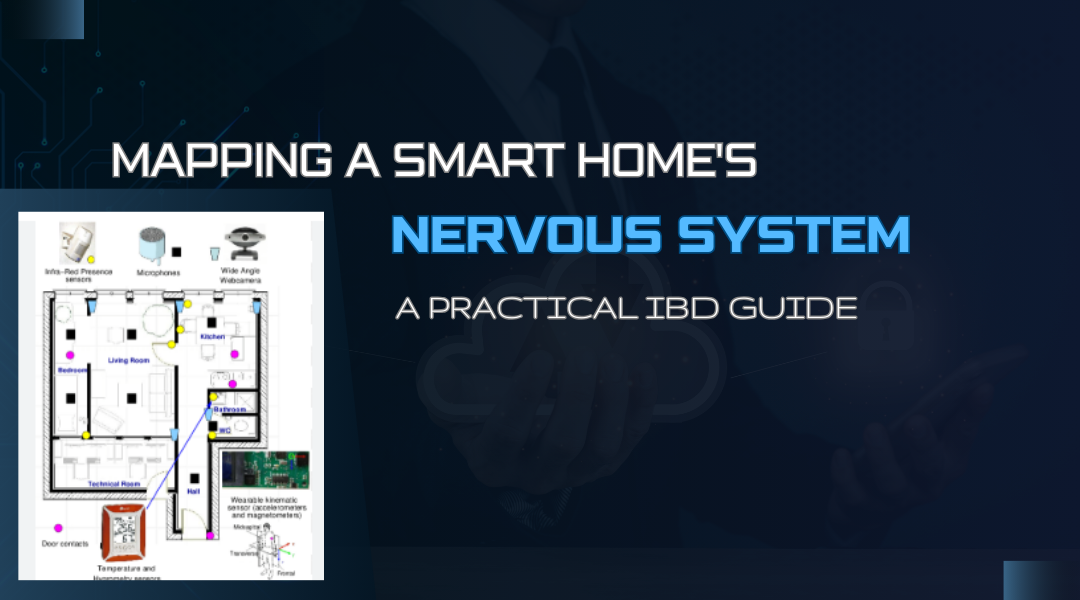
- The Senses: Multi-sensor units (combining motion, light, temp in one device)
- The Muscle: Smart relays (for lights/appliances with fail-safe modes)
- The Voice: Voice assistant gateway (because Alexa shouldn’t crash your HVAC)
Step 1: Identify the Real Connections
Forget generic boxes labeled “sensors.” We need to model actual communication paths:
Critical Links That Often Get Missed:
- The 2.4GHz vs 5GHz WiFi divide (cameras hogging bandwidth from sensors)
- Power-over-Ethernet vs battery-powered devices
- Local processing vs cloud dependency (what works during internet outages?)
Example: A motion sensor might have:
- Zigbee radio port (for normal operation)
- Hardwired backup port (direct to alarm panel)
- Battery status output (so you know when it’s about to die)
Step 2: Define the Communication Handshakes
Every arrow in your IBD should answer three questions:
- What’s being sent? (Data type, format)
- How often? (Update frequency)
- What happens if it fails? (Timeout behavior)
Real-World Port Configuration:
1. Primary Data Channel
Multisensor → Hub
- Data Type: Environmental Data (JSON formatted)
- Payload Example: json{ “temp”: 23.5, “humidity”: 62, “air_quality”: 112 }
Protocol Specifications:
- Update interval: 30 seconds
- Retry mechanism: 3 attempts on failure
- Transport: Wireless (WiFi/LoRa)
2. Critical Safety Channel
Bypasses all normal data processing
Multisensor → Alarm Panel
- Data Type: Emergency Alerts (Plaintext)
- Payload Example:
"FIRE_DETECTED"
Protocol Specifications:
- Priority: Instant transmission (interrupt-driven)
- Connection: Hardwired (failsafe circuit)
Step 3: Map the Failure Modes
A good IBD shows not just ideal flows, but failure paths:
Common Smart Home Pitfalls to Model:
- Cloud service latency causing light commands to stack up
- Zigbee mesh network gaps creating dead zones
- Voice assistant misinterpretations triggering wrong devices
Pro Tip: Use dashed red lines for fallback communication paths in your diagram.
The Complete Smart Home IBD
Here’s how the pieces actually connect in a robust system:
Core Hub Connections
- [Voice Gateway] ←(Cloud Sync, HTTPS)→ [Mobile Apps]
Wired Connection
- [Security Camera] ←(PoE IEEE 802.3af)→ [Hub]
Wireless Connections
- [Multisensor] ←(Zigbee 3.0, 2.4GHz)→ [Hub]
- [Smart Lock] ←(Dual-mode: Zigbee + WiFi 5GHz)→ [Hub]
- [Light Switches (1-N)] ←(Thread 1.3, 2.4GHz)→ [Hub]
Gateway Connections
- [Hub] ←(Local REST API)→ [Voice Gateway] ← (Cloud Sync)─[Mobile Apps]
Key Features Worth Noting:
- Dual-protocol devices (like the lock using both Zigbee and WiFi)
- Wired backbone (PoE cameras don’t choke the wireless network)
- Local fallback (Voice commands work even without internet)
- Clear protocol segregation (Thread for lights, Zigbee for sensors)
Stress-Testing Your Diagram
Ask these hard questions about your IBD:
- When the WiFi router reboots, what still works?
- If three family members give voice commands at once, where’s the bottleneck?
- How does a firmware update propagate through the system?
Case Study: A client’s “smart” home kept unlocking doors randomly. The IBD revealed their Z-Wave mesh was routing through a malfunctioning light bulb – a connection no one had thought to diagram.
Your Turn: Fix This Broken IBD
Here’s what a problematic smart home IBD might look like:
[All Devices] → [WiFi Router] → [Cloud] → [Phone]
What’s wrong with this? (Hint: Everything. No protocol distinctions, no local control paths, single point of failure.)
Try redesigning it with:
- Wired and wireless separation
- Local processing options
- Clear protocol labeling
Beyond the Diagram: Making It Real
The best IBDs become living documents that guide:
- Installation (Technicians know exactly how to wire things)
- Troubleshooting (You can isolate communication breaks visually)
- Expansion (Adding new devices won’t break existing functions)
Remember: Your smart home should make life easier, not create new problems to solve. A well-crafted IBD is the first step toward that goal.